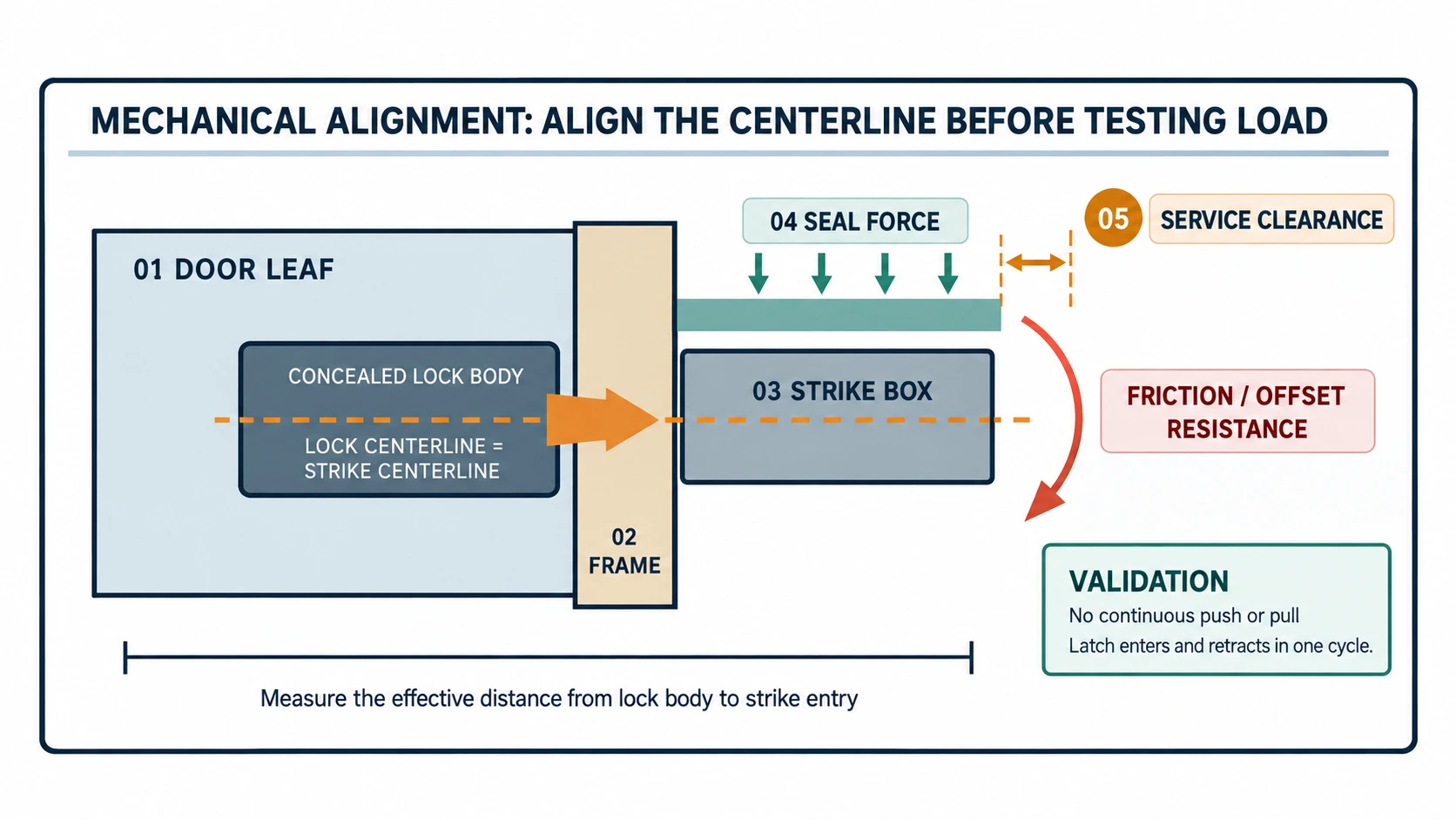
Prepared by the WAFU Technical Center for project engineers, procurement teams, installers, system integrators and OEM/ODM brand owners. This guide explains the validation method; formal product datasheets remain the source of truth for product-specific limits.
A concealed lock can fit inside a door and still fail in service. Centerline error, strike position, door sag, seal compression and installation tolerance all change the load seen by the drive. Treat mechanical alignment and drive-load validation as one project gate before volume release.
Contents
- Five geometry checks
- The mechanical load path
- Tolerance stack-up
- Sample drive-load testing
- WF-019 and WF-026 validation focus
- RFQ and release records
- Conclusion
1. Start with five geometry checks
Measure the lock-body centerline against the strike-box centerline. Record door thickness, lock height, backset, closing offset, handing and hinge condition. An open-door test only proves that the internal mechanism runs without frame resistance.
Confirm latch entry, side rubbing, bottom impact and whether the door must be pushed or pulled during locking or unlocking. If manual pressure is required, inspect the door geometry and strike position before blaming electronics.
Heavy or frequently used doors may sag over time. Hotel, apartment and fire-door projects may also add spring force through seals. Reserve maintenance space for the battery, cover, tools, wiring and emergency release.
2. Map the mechanical load path
The drive sees a combination of latch friction, seal return force, door offset, internal transmission resistance and installation error:

Use  only to understand the relationship between resistance, lever arm and efficiency. It is not a substitute for a product torque test.
3. Use tolerance stack-up to predict risk
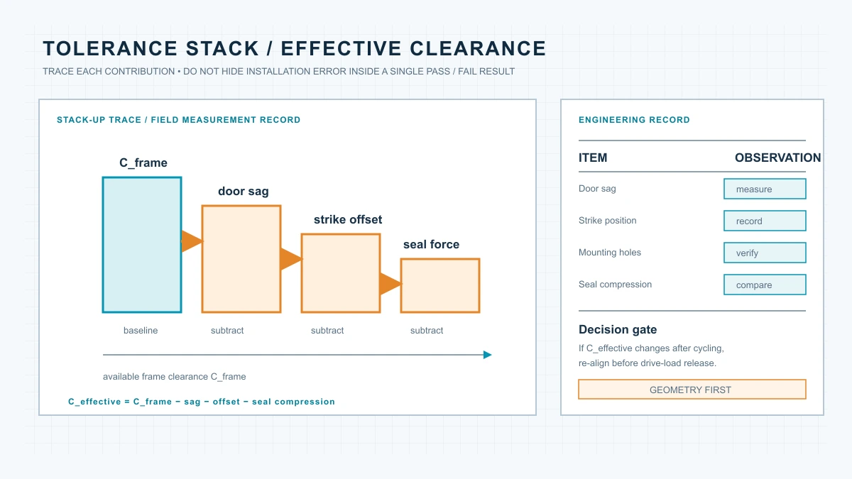
Door sag, strike offset, mounting error and seal compression may look minor individually, but together they reduce the effective clearance:

Track door thickness, centerline height, latch entry, seal condition and maintenance clearance before and after sample installation and cycle testing. Record measurements, not only “pass” or “fail”.
4. Design the sample drive-load test
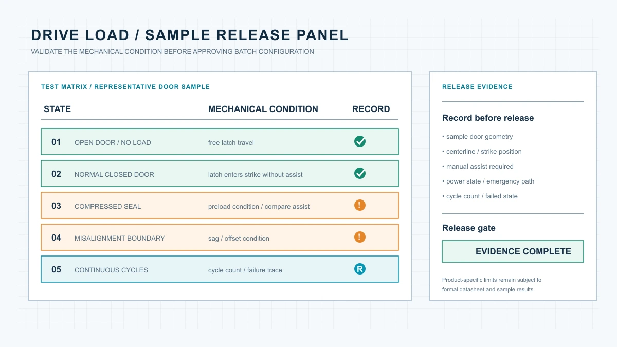
Test four states: open-door no-load, normal closed-door, compressed-seal or other high-resistance boundary, and slight misalignment. Record one-cycle completion, full latch retraction, manual assistance, sound change and power condition.
For repeated cycles, record cycle count, failures, door state, intervention and adjustment history. Do not hide an intermittent failure by restarting or replacing batteries; inspect the latch, strike, door and seal relationship.
5. Validation focus for WF-019 and WF-026
WF-019: keep deployment simple
Current product information lists two AA batteries and 433 MHz remote control as the base configuration. Confirm cavity space, stable alignment, battery access, real-site range and whether fingerprint, PIN, NFC or App modules are standard or optional in the quoted configuration.
WF-026: verify redundancy as a complete force path
Current product information lists a dual-system, dual-motor architecture and Grade C cylinder. Test both drive systems, check mechanical interference, document battery ownership and emergency release, and define the response to one system fault. Redundancy does not remove door-offset friction.
6. Put results into the RFQ and release record
Capture door material, thickness, handing, hinges, seal, existing lock and strike dimensions, then add lock position, centerline, service space, emergency release, wiring route and test evidence.
Replace “sample works” with a verifiable condition: on the representative door, the latch completes locking and unlocking without continuous manual pushing or pulling, and the measurement, adjustment, service and emergency records are complete.
7. Conclusion: validate the door before the batch
Measure the door and frame, confirm the centerline, inspect the latch path, assess seal and sag, run open and closed-door tests, then test boundary conditions and repeated cycles. Only after those results are recorded should the project lock its batch configuration.
For WF-019, WF-026 or another OEM/ODM configuration, use the formal technical file and representative sample as the final authority.